For PART 1 click here
For PART 2 click here
For PART 3 click here
—
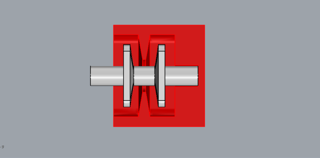
For the fourth iteration I built on the 3rd one but this time I inverted the shape of the inflation chamber. Made the walls thicker and and the inflation chambers much thinner and acute. Below is an image of the cross section of this actuator.
This illustration shows the different approaches in trial 3 and 4cross section view of one segment of the mold.
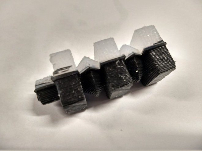
I only decided to print one segment of the mold to make de-molding easy.
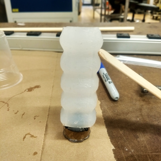
Unfortunately the Silicone hadn’t cured even after 7hrs!
By the time I got to casting the silicone, the 00-50 grade which we had in class had gotten over. I bought the 00-30 variant since it had a cure time of 4hrs, only 1 more hour than the 00-50 grade. But even after 7+hrs or curing time it was still runny on the bottom end of the cast.
I have a feeling it probably has to do with the cooler temperature on the ITP floor. I think it cures faster at higher temperatures. I plan to recast this actuator on a slightly warmer day and continue this process through the summer break.
For PART 1 click here
For PART 2 click here For PART 4 click here
For the third iteration I wanted to model something after the accordion structure.
This video below shows the accordion shaped actuator extending linearly
I took inspiration from this but decided to add some solid chunks of silicone in between to add some stability to the actuation.
As seen in the CAD model above, the cuboidal blocks of silicone do not inflate. They work as internal bracing elements. The blocks also serve as channels for the proposed external restraints to pass through.
Mold design for the actuator with the outer part and inner core.3D printed piece of the mold. The red wire seen on the left is to keep the cantilevered end of the inner core from touching the outer mold part.I casted only one half of the actuator first and decided to color the other half.Fully casted actuator, there were a few tears toward the end of the casted piece so I had to cut it in half.
As you can see, this iteration achieves a good amount of linear extension but it inflates in a rather ugly manner. Also it doesn’t inflate evenly. I later found out from Kari that silicone has a tendency to do that, maybe the wall thicknesses were slightly uneven and once it inflates beyond a threshold, it creates microscopic tears which irreversible alters the behavior of the actuator.
I tried inflating the actuator with external restraints (white wire attached to the actuator). As you can see it did successfully turn linear motion into bending motion. I just needed to refine the inflation aesthetics in the following iterations.
For PART 1 click here
For PART 3 click here For PART 4 click here
—
For the second iteration I wanted to test out a helical spring shape for the inner core of the actuator. The idea was to inflate a spring shaped hollow chamber to achieve linear extension, much like stretching a helical compression spring.
I quickly made a spring with thick aluminium wire coiled around a chiselI put together a mold with these basic components, all picked up from the junk shop. The spring formed the inner core, the aluminium tube is the outer mold and the cardboard piece formed a conical end of the actuator for air inlet.Actuator is casted and set aside for curingAnd now the hardest part was demolding the inner spring.Again, with this one too, I did achieve linear actuation but the whole form was inflating much more than I liked. I was still happy with the overall form of this piece. I’d like to explore this aesthetically in the future.
For PART 1 click here
For PART 3 click here For PART 4 click here
For PART 2 click here
For PART 3 click here For PART 4 click here
—–
For my finals for soft robotics class I want to make a system of modular soft actuators which can be combined together to perform different functions.
The soft modular system is an effort to create a plug and play system with soft robotics which is a very fabrication intensive process. I am also thinking of this system as working like an educational tool or toy to introduce kids and adults to the field of soft robotics. This will be to soft robotics, what K’nex is to mechanics or Little Bits is to electronics. Ideally, these blocks should also be compliant with other forms of robotics where they can be easily integrated.
Multiple modules for a common function
This approach required me to fabricate multiple modules which would come together to carry out a single function. Like putting together the pieces of a puzzle.
Same module, Multiple functions In this case I will make multiples of the same module which can perform differently with simple modifications or combinations. I found this approach to be more interesting and feasible, given the time frame of 3 weeks
The image below demonstrates my idea of a kit with different modular components.
The kit mainly comprises of linear silicone actuators, internal restraints, wheels, end caps, etc.
The different components can be fit together to create different robots or mechanisms as shown in the animation below.
clockwise from top left : Rope climbing robot, gripper, CG wheel, crawling robot.
The chart below explains the motivations and rationale behind the project.
Most common actuation methods used in soft robotics are linear (forward and backward) and bending. I realized I need only design a linear actuator and use a mix of external and internal constraints to achieve different kinds of motions. So the actuator module remains same but the variety of motions is brought about by modular restraints.
Update : April 3rd
To test out the idea I designed a mold in Rhino to cast a basic actuator. I also wanted to test the coupler design which would enable the modularity and interfacing between different modules.
Dark grey part is the actuator and the light grey covering is a cross section of the mold designFinal molding assembly file ready for 3D printing
Shown in red in the image above is the coupler in hard plastic which is assembled with the actuator. The coupler has 4 arms which serve as hooks for different restraints. The coupler is slightly oversized to achieve a tight fit with the silicone actuator. In the final design the coupler should be in-molded with the silicone part. The 4 holes seen on the silicone part at the corners is the channel for the internal restraint to pass through.
Update : April 7th
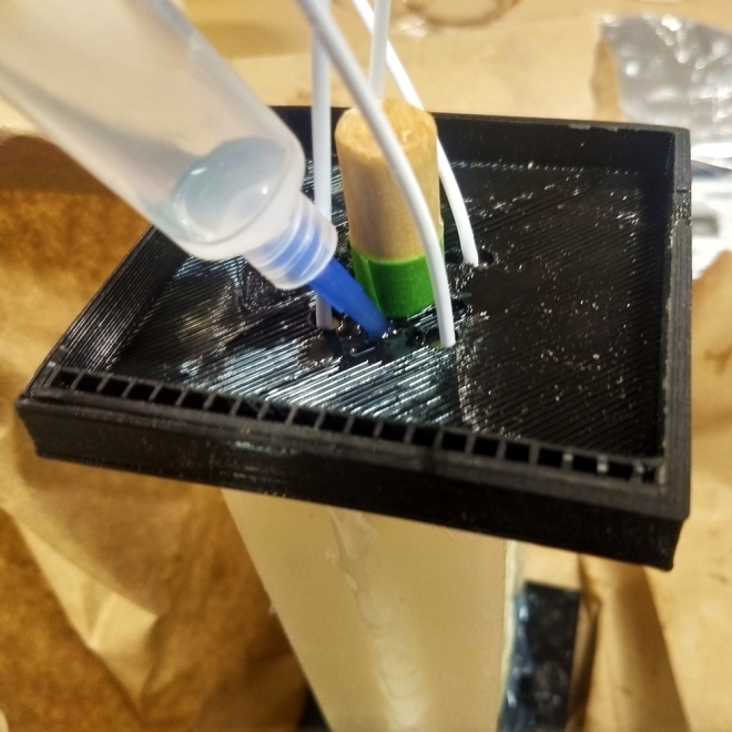
Main body of the cast is ready for molding. I inserted two sticks in each half to form the channel for the restraint.
I also made small holes to let the air out and get the silicone moving more freely.
One half of the mold assembly. The green stick in the center forms the central inner air cavity.
Unfortunately the silicone started leaking from the bottom due to increasing pressure. I decided to let it sit and re-cast it the next day.
Update : April 8th
Was happy to see at least half of the actuator was casted. If anything it was a good run for testing the quality of the cast. Also gave me a much better idea for dis-assembly.
After de-molding, I reassembled the mold and plugged the holes and the edges with hot glue this time.
Parallely I cleaned up the half casted actuator for early testing of the actuation.
Tested assembling the coupler for fit.
I decided to plug one end of the actuator with more silicone and set it aside for casting.
3 hours later…
The actuator is sealed from one end
On the side, I injected more silicone into the mold which was still curing, to fill it up completely and compensate for some of the silicone which leaked at the bottom.
Update : April 9th
Final casted actuator. The red cable demonstrates the restraint mechanism.
I was able to achieve some linear actuation but not without overall inflation.
For PART 2 click here
For PART 3 click here For PART 4 click here
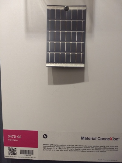
We visited the Materials Connexion library to look at emerging materials we could work with for our finals for soft robotics class.
I primarily looked at Silicone materials as I plan to use Ecoflex extensively for my final project. Listing down a few materials and processes that I am interested in exploring. Some of the materials listed below were found on the online library.
For my final project for soft robotics class I am interested in making a soft robot with an exoskeleton. The idea is that the exoskeleton will protect the soft materials from punctures and cuts. The robot would still be based on soft actuation mechanisms. To test out the idea I thought of making a small 3 prong gripper with an exoskeleton. The plan was to 3D print the grippers exoskeleton in a flexible material and fuse that with the inner silicone gripper in the silicone casting process.
The above picture shows a 3D model of the 3 pronged gripper. The red part being the tough but flexible exoskeleton and the inner light grey part being the silicone casting, this is the part that is actuated. The exoskeleton being flexible, conforms to the silicon inflation.
I took these files to 3D print. But it turned out that the 3D printers were not capable of printing in flexible material. So as a workaround I printed the upper cylindrical part and the 3 flaps separately and thought of joining them with black electrical tape.
Pictured above is a CAD model of the mould for casting silicone, the sloping feature to the right is the spout from where the silicone will be poured.
the silicone casting mould is attached to one of the 3 flaps on the exoskeleton as pictured above and the silicone is poured from top (indicated by the black arrow)
3D printed parts ready for casting!
I poured in the silicone and set the part aside for curing. I only applied mould release to the inner part as I wanted the silicone to adhere to the gripper flaps. I have to admit, the silicone pouring process was extremely difficult as the size of my nozzle was very small. The silicone wasn’t flowing freely into the cast, instead it was just sitting at the nozzle opening after a point which made me think that the silicone was fully poured in.
As you can see, it was a massive failure! But it left me with some valuable learning.
Silicone wont naturally bind to any surface. I should create a physical/mechanical bond to secure the two together. One possible way of doing that is to create holes on the one surface (usually the harder surface) and let the silicone flow through it over to the other side. On the other side the silicone needs to be fixed in place with a slight flange.
The nozzle for pouring silicone should have a good enough opening, at least 10mm will make it easier to pour in.
Incorporate small runners throughout the mould on the opposite ends of the nozzle to let the air out as you pour the silicone. This minimizes bubbles from forming in the silicone and at the same time helps the silicone flow into the mould. Sometimes if the nozzle is too small to clog the silicone and the mould doesnt have any means of releasing the air the silione will not pour in.
An alternative way of casting this would be to first pour the silicone in its mould and then secure it to the flap, that way i could have easily poured all the silicone into it’s mould.
Amena and I visited Target to do some research on some soft goods for inspiration. The intention of this exercise was to identify products that use soft materials to use as idea triggers for your final class project.
Since I am interested in making a soft robot with an exoskeleton to protect it from wear and tear and getting punctured or cut, I was on the lookout for similar products with a mix of hard and soft.
To be honest, I didn’t find too much variety. Most of the goods were essentially soft toys. Below I am listing down few of the things that were noticed. I might also add to this list, references found on the Internet or other sources.
1. Soft + hard shell sky projector toy
A soft elephant with a hard shell on top. Underneath the hard shell is high power LED which projects the star shaped cut outs on the shell all over the room. This inspires me to think of my retracting robot from an assembly point of view. To first cast the silicone, pack all the electronics inside it and then glue the exoskeletal parts at the end.
—-
2. Soft toy puppy with embroidered graphics
Not much going on here. But the graphics treatment had me thinking about incorporating surface graphics and and textures in my robots. I am eager to explore combining different castings with varying colors and textures on the same robot to differentiate its various parts. I will need to first cast all the colored/textured components separately and then find a way to insert mould them into the larger and final robot body. This will add some depth to the otherwise bland looking soft robots that we normally see.
—-
3. Suction cup balls
The classic childhood toy. The suction mechanism is very interesting when I think about it in a robotics context. Would be interesting to explore mechanisms where the suction can be introduced and taken away, in a programmed way. I think FESTO already does that in their octopus tentacle inspired gripper.
—-
4. Modular toy
A modular slithery toy! That actually gives me a very exciting idea of building modular blocks of soft robotic actuators to build custom robots! Much like Oscar but without the creepiness and gross living tissues, using silicone and other inflatable materials instead. I might decide to take this as my final topic.
—-
5. Nice texture
I like the textural quality of this product. I can imagine a wall mural with dynamic, kinetic hair like structures, each actuated individually and can be programmed to create soothing wave like patterns!
After watching BBC’s Planet earth, over and over, with the same amount of amazement and excitement as seeing it for the first time, it is really hard to pick a single favorite organism to write about. Our planet seems like an bustling inter-galactic rave with strange creatures, much bizarre than Burning man! Each on their own trip, donning trippy costumes and displaying bizarre antics!
But for the sake of this assignment, I will pick the Australian thorny devil!
This menacing creature!
It’s called the thorny devil for a reason! But as menacing as this being may appear, it’s actually quite tiny and feeds on ants alone. It sits and waits near ant colonies or ant trails, and with it’s sticky tongue, sucks up poor ants religiously going about their daily routine, one by one, much like a gripper atop a conveyor belt on an assembly line. It can consume thousands of ants in a day!
Not so devilish after all!
This creature has a variety of tricks up its sleeve to ward off predators and survive in the hellish, arid Australian desert. From inflating its lungs to bulk up in physique to having a false head on its back to changing its color. But the one I find most interesting is that it is hygroscopic (moisture attracting) which means that it can drink water through its feet! The spikes and tiny grooves spread all over its body, concentrate dew and channelize it toward its mouth through capillary action. Watch the video below if you don’t believe me. (3:30 – 4:30, if you are in a hurry)
It’s a fascinating survival mechanism! Wasting energy in the desert can come at a significant cost, so the devil has evolved ways to eat and drink with minimum wastage of energy.
I can imagine a possible method of constructing frugal temporary shelters in a similar fashion. Much like how stalagmites are formed! But instead of solid columns being printed by dripping calcified water from top, my (hypothetical) process employs capillary action to suck up calcified water (or some such engineered liquid) against gravity to construct columns for a small shelter. Such a process would need minimum manpower and harnesses simple physics to automate the construction process, enabling multiple shelters to be constructed parallely. The entire process would look a bit like the time lapse below. But instead of just one column, you would need at least 3 of these to construct a viable house.
The task flow of this process would be –
1. To have a bed of calcified water or engineered liquid, about as big as you’d want the footprint of the house to be.
2. Place starter bricks which initiate the capillary action in a vertical direction.
3. The liquid will suck up to the surface of the brick and harden as it rises.
4. Starter bricks come in a variety of shapes, much like piping joints. Y, T and L would be the most desirable choices. Place these shaped bricks on top of a column to channelize it in different directions.
5. Once the skeleton is ready, clad it with appropriate sheets or even construct entire walls with the same method.


 Not much going on here. But the graphics treatment had me thinking about incorporating surface graphics and and textures in my robots. I am eager to explore combining different castings with varying colors and textures on the same robot to differentiate its various parts. I will need to first cast all the colored/textured components separately and then find a way to insert mould them into the larger and final robot body. This will add some depth to the otherwise bland looking soft robots that we normally see.
 The classic childhood toy. The suction mechanism is very interesting when I think about it in a robotics context. Would be interesting to explore mechanisms where the suction can be introduced and taken away, in a programmed way. I think
  A modular slithery toy! That actually gives me a very exciting idea of building modular blocks of soft robotic actuators to build custom robots! Much like
 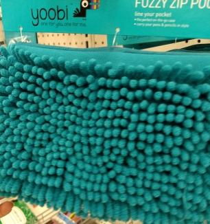 I like the textural quality of this product. I can imagine a wall mural with dynamic, kinetic hair like structures, each actuated individually and can be programmed to create soothing wave like patterns!

